Plates
A plate is defined as a solid structure in which two dimensions are
much greater than the third (thickness).
The medium surface equidistant from the faces of greater dimension
is called the medium plane of the plate.
The state of load of a plate is called "plate state" if the loads
act only in the normal direction to the medium plane and if bending
moments are tangential to it.
A classical example of this type of structure is the construction
slab used in buildings.
There are various theories for solving plate problems. Calsef uses
the Reissner-Mindlin theory, which is explained at length in Cálculo
de Estructuras por el Método de los Elementos Finitos by Eugenio Ońate.
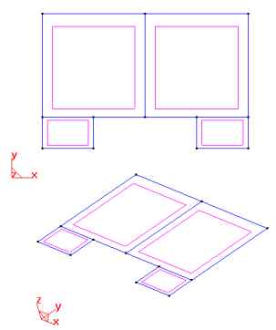
Defining the geometry:
Since this is a two-dimensional problem, the geometry must be defined
within the plane Z=0.
Following is the geometry of a system of two contiguous slabs with
cantilever ends.
Just as in the plane state, the geometry is defined by a series of
lines limiting the surfaces belonging to the X-Y plane, with Z=0.
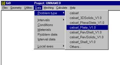
Once the geometry is defined, the type of plate problem may be
selected.
Boundary conditions ("Conditions")
This type of problem has a rather special coordinate system for
assigning the boundary conditions and interpreting the results.
This system corresponds to the theories explained in the specialized
bibliography. For greater detail on this subject, please consult
these books.
In this type of problem, the global axes are the only ones of
interest since the loads and constraints are defined with reference
to them.
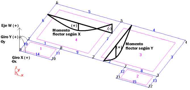
The following drawing shows the definitions of the global axes. Here,
the vertical axis (corresponding to the conventional Z axis) is labeled
the W axis.
As to the X-Y plane, the directions and labels of the axes are
maintained; however, it must be kept in mind that within this plane,
only normal-direction forces, bending moments, and constraints of
rotation exist.
As to the signs of the loads, whether the load is on points, lines,
or surfaces, it will be considered positive provided it is in the
positive direction of W.
As to the signs of the bending moments, they will be considered
positive (as usual) if they provoke tension on the lower fibers of
the medium plane.
So, the particularities of this coordinate system are 1) if there is
a rotation around the conventional X axis, in this new system it will
be a Y rotation (Qy) and 2) if there is a bending moment around the
conventional Y axis, it will provoke a deformation (rotation) labeled
X (Qx).
The sign of the bending moments follows the classical sign convention.
It is considered positive if the bending moment produces tension in
the lower fibers.
The various boundary conditions available are the following:
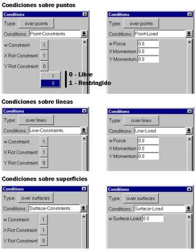
Below, is a figure showing the conditions applied to our example:
1) simple supports (W constraints on the lines) and 2) a surface load
on each of the four slabs, with W = -50 because it is a gravitational
load.

Defining the materials ("Materials"):
Materials must be assigned to the surfaces defining the problem.
Care must be taken not to assign a material to an entity (lines) that
is only needed to define the surface and the boundary conditions.
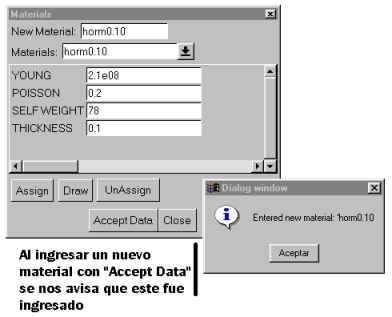
Concrete will be the material in the present case. However, two
different plate-thickness dimensions are involved. This calls for
two material definitions, con0.1 and con0.2. First enter one, with
its corresponding values, and then the other, with its corresponding
values. Finally, click on "Accept Data" to enter the data as new.
Note that this data will be saved only for the current problem.
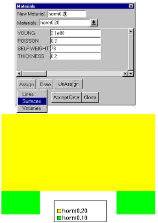
Once the new materials have been defined, they must be assigned to
their corresponding surfaces.
GiD's graphics tools may be used to visualize the final configuration
of the materials, thus ensuring that they have been assigned correctly
and that no surfaces have been omitted.
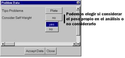
Specific data of the problem ("Problem Data")
In this case, notice that the problem type may not be changed, that
only the self-weight may be considered in this analysis.
The self-weight acts in the negative direction of W.
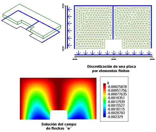
Generating the mesh ("Meshing")
The example is solved with a mesh composed of linear triangular
finite elements (DKT), not quadratic.
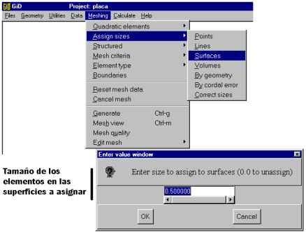
Since the density of elements at the cantilever ends needs to be
increased, a certain size element must be assigned to the surfaces
defining this zone. Note that an element size may also be assigned
to a line or to a point so that the mesh will be of the selected
size near these entities.
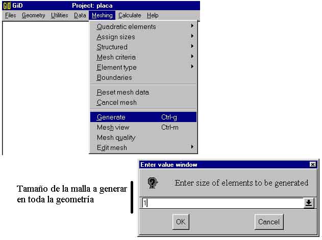
Once the size of the elements has been selected for the surfaces
under consideration, the mesh is ready to be generated.
As a last step, click on "Mesh View" to visualize the mesh.
The densification of finite elements can be seen on the surfaces
of the cantilevers.
Finite elements available:
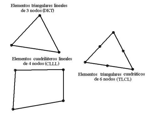
In order for Calsef to be able to solve the problem, the mesh must be
generated with only these types of elements.
To use TLCL elements, a mesh of quadratic triangular elements must be
generated.
Results:
Once the structure is solved, the results may be visualized using the
options available in GiD. Nevertheless, it is important to know
what results to expect:
· Deformation along W, or deflection (Z-Def)
These deformations along W (i.e. vertical, also called deflection)
have a positive sign according to the W positive sign convention.
In the SI, these deformations are expressed in meters.
· Rotations around X (X-Rot)
· Rotations around Y (Y-Rot)
These rotations have the directions indicated in the sign convention.
This means that rotation around X generates moments in this same
direction.
In the SI, these rotations are expressed in radians.
· X bending moment per unit of transversal length (Mx)
· Y bending moments per unit of transversal length (My)
· Torsion moments per unit of length (Mxy)
The bending moments are per unit of transversal length and, expressed
in the SI, are in Nm/m.
They have the directions previously defined. The positive sign will
be that which generates (ex)tension in the lower fibers.
· Shearing stress ZX (Qzx) - only in CLLL and TLCL elements
· Shearing stress ZY (Qzy) - only in CLLL and TLCL elements
The shearing stress is expressed in force per unit of transversal
length, which, in the SI, is in N/m.
The sign of the shearing stress is shown as follows:

Go back