Case Study
In this chapter various finite-element solutions are outlined. These
are applied to a well-known problem.
Problem statement:
The following problem involves an isostatically-supported T-beam with
a uniformly distributed load on the upper surface.

This problem has a well-known solution and can be easily calculated
step by step.
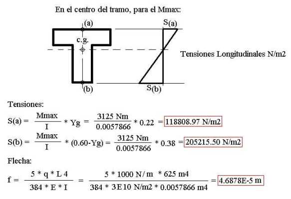
Theoretical solution
The figure above shows the bending moments, geometric parameters of
the cross-section, and materials characteristics, as well as a
cross-section of equal (moment of)
inertia, which will permit us to compare the results by considering
the beam as a plate with the dimensions of this cross-section.
Following are some easily calculated values:
Solution as a Planar State Problem ("viga_ept.gid"):

For this mesh configuration, the following results are obtained:

Following are other results that have been calculated:

It can be observed that as the density of the mesh increases, the
results begin to differ more from the theoretical ones. In order to
improve the model, move the boundary conditions (supports) to the
position of the neutral axis (fiber) of the beam.

With this adjustment, better results are achieved. But again, as the
density of the mesh increases, the results differ more. Therefore,
the boundary conditions (supports) must be adjusted exactly to the
position of the neutral axis in order to obtain an accurate solution
for the deformation.
8.4 Solution as a Plate problem ("viga_placa.gid"):

Attention should be paid to the fact that the discretization of the
problem is carried out using an equivalent geometry and in such a way
that the new cross-section has the same inertia as the original one.
The description of the load must undergo a conversion in such a way
that a load of 1000N/m of beam length becomes a load of 1667N/m2 on
the upper surface of the beam, which measures 0.60 meters wide.
For this mesh configuration, the following results are obtained.

Notice that in this model the bending moments are expressed per unit
of length. Therefore, in order to convert this value back to the
reality in which we are working, it must be multiplied by the width.
For example, the maximum bending moment of 5211.5Nm/m indicated in the
above figure is converted, in this case, to 5211.5Nm/m*0.60m=3126.9Nm,
rather close to the theoretical results.
Following are other results that have been calculated:

Solution as a three-dimensional problem ("viga_sol3d.gid"):
Given the following three-dimensional geometry,

a structured mesh of linear hexahedron with 8 nodes has been generated.

For this mesh configuration, the following results are obtained.

Solution as a shell problem ("viga_lam_tens.gid"):
Here the geometry is composed of shells representing the medium
planes of each of the two parts of the beam:

The following mesh has been generated.

For this mesh configuration, the following results are obtained.

Keep in mind that these results are given in relation to the
Global axes.
Attention must be paid to the direction of the longitudinal stresses
provided they are n reference to the local coordinates.
As pointed out previously, for this shell the local axes are

Therefore, the longitudinal stresses are in the X direction.
The last item to clear up is the expression of the results obtained.
Provided they are expressed as force per unit length of the
cross-section, they must be divided by the thickness of the
cross-section, thus obtaining force per m2. For example, in the
above figure the thickness is 0.2m; accordingly, the maximum tensile
stress is 38065 N/m / 0.20 m = 190325 N/m2