Air-bridge
Programa PROVA'T (2012-13)Development, validation and
transfer to market of a prototype of
Air-Bridge for surface transport
vehicles


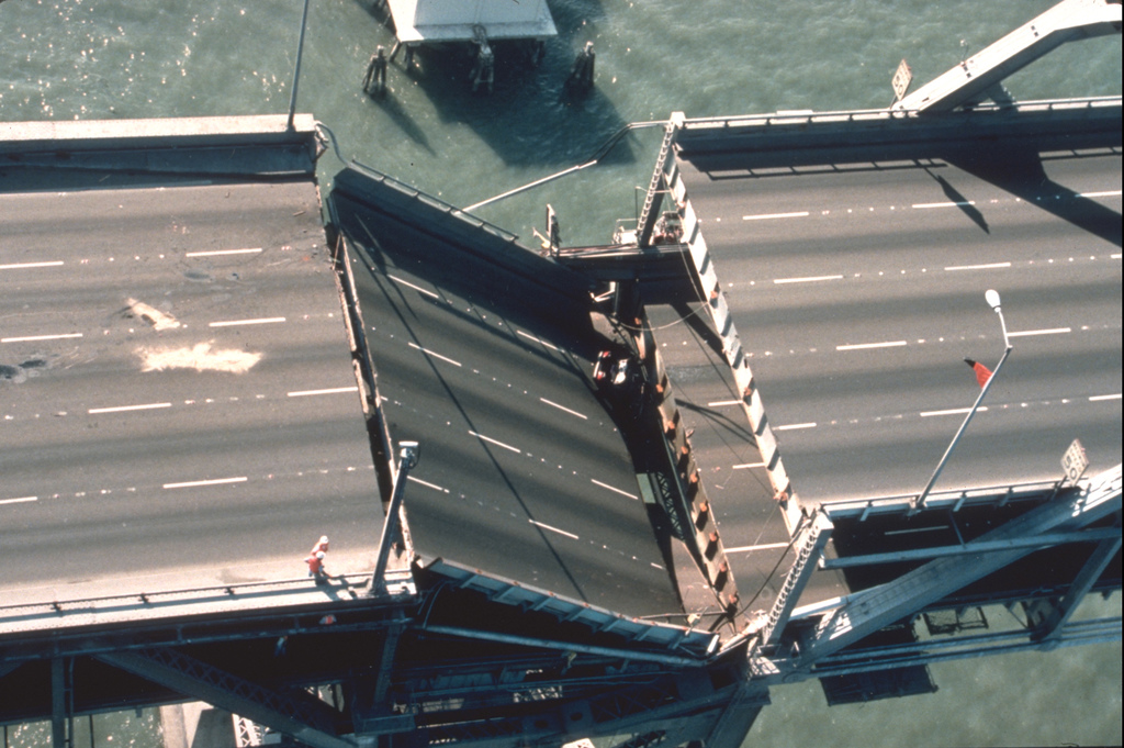
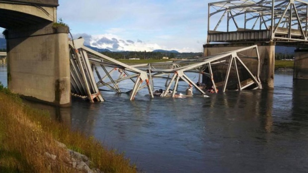
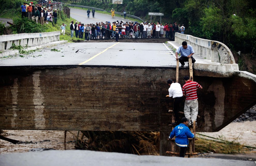
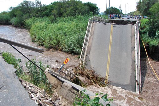
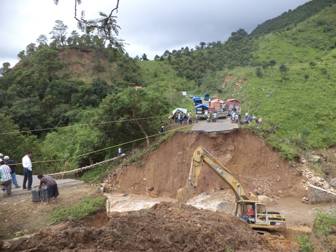
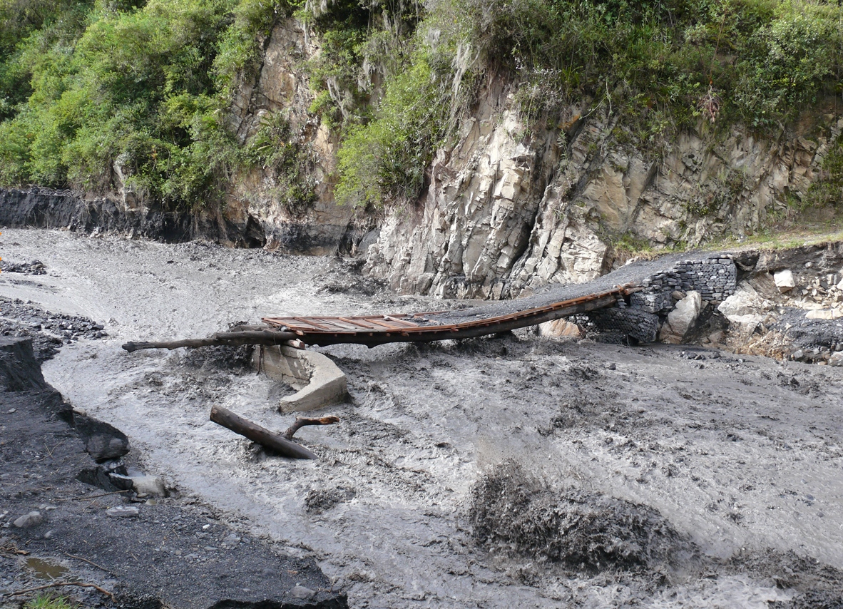
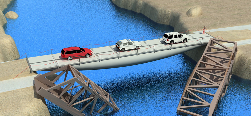
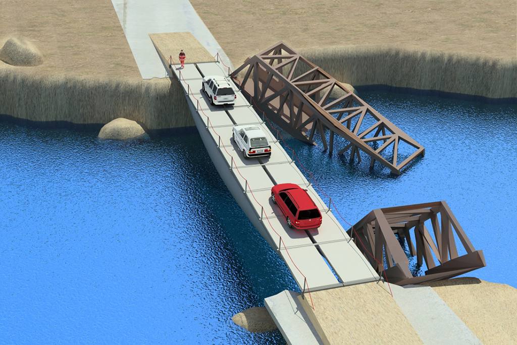
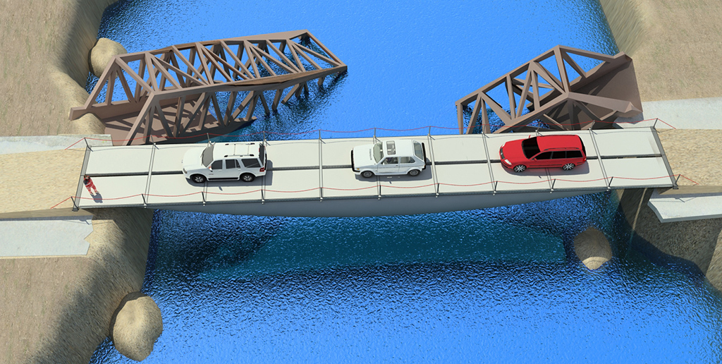
In the event of natural disasters, the first step that needs to be done is the reestablishment of the bridges.
When devastated areas have not communications, it is not only difficult to transport and evacuate their habitants, but also the supply of resources needed to support international aids.
In such situation, the speed, ease and efficiency of deployment are essential.
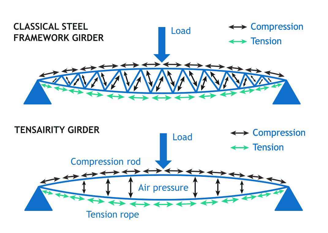
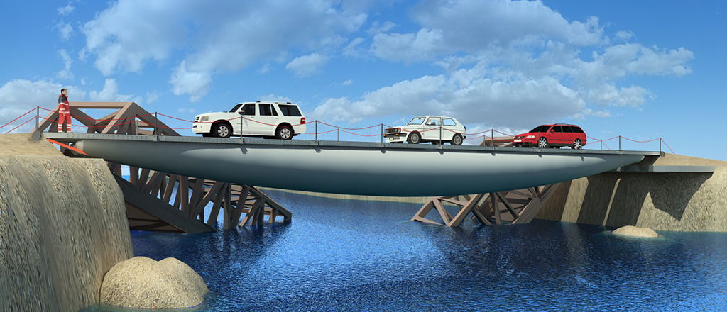
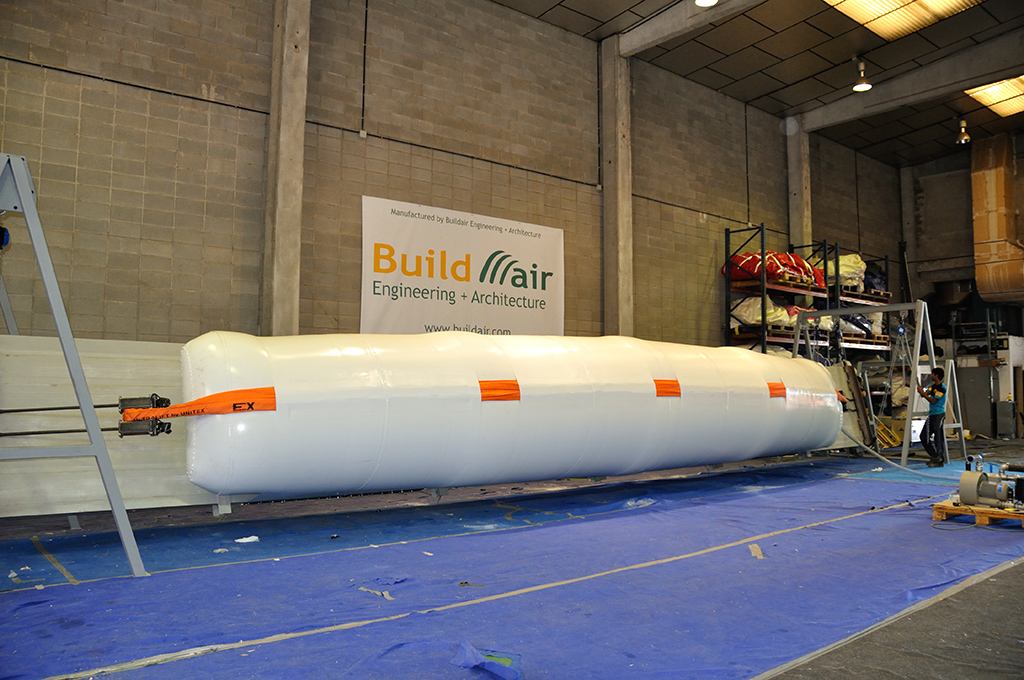
Inflatable ultra-lightweight fast-deployable bridge for surface transport vehicles, which utilizes low-pressurized air-filled beams as the primary load-bearing structural spanning members.
TENSAIRITY = TENSION + AIR + INTEGRITY
THE LIGHTEST SYSTEM IN THE MARKET!
Facilitate emergency evacuation tasks and communication reestablishment of devastated areas due to natural disasters.

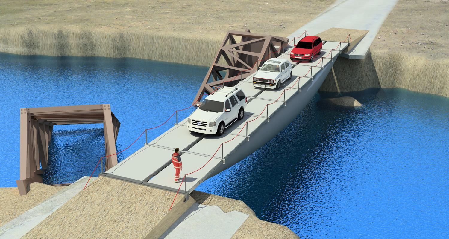
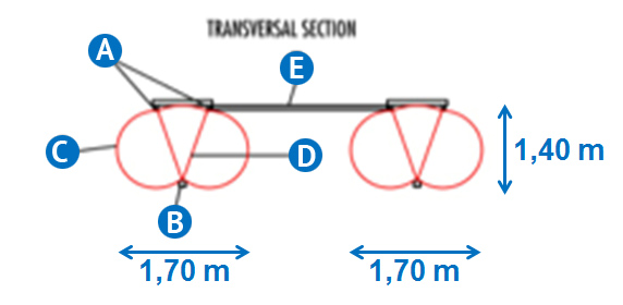
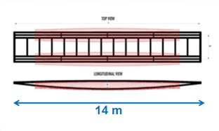
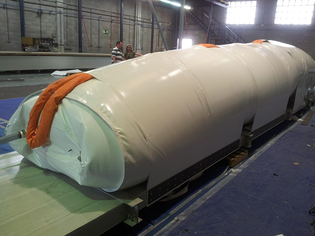
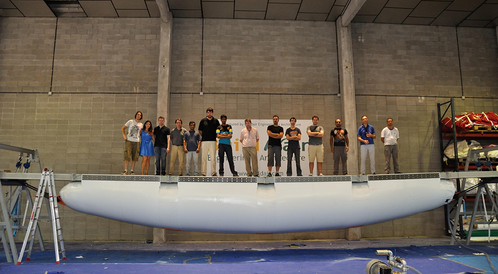
The bridge consists of 2 inflatable beams 14 m long and 1,70 m wide joined together.
*
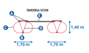
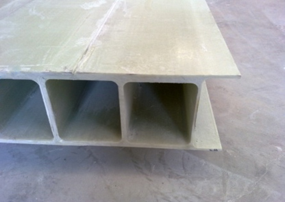
*The projected structure consists essentially of four main elements:
| Dimensions | Length 14 m Width 3,5 m |
Similar to other alternatives |
| Inflation pressure | 175 mbar | 12 times less pressure than a vehicle wheel |
| Weight | 5 tn | Up to 7 times lighter than alternatives |
| Weight/m2 | 100 kg/m2 | Up to 7 times lighter than alternatives |
| Vehicle load | 30 tn | Ratio load/weight of 7 to 1 |
| Storage volume | 12 m3 | Up to 5 times smaller than alternatives |
| Deployed volume | 78 m3 | Ratio deployed/storage volume of 6,5 to 1 |
| Larger element | 2,00 x 1,80 x 0,20 m3 | Weight 185 kg |
| Set-up effort | 8 workers / 8 h | Up to 5 times smaller than alternatives |
| Use of heavy machinery | Not required | Always required in other alternatives |

The main distinguishing features offered by the Air-Bridge are:
| 1 | Inflatable technology, completely innovative for emergency bridges |
| 2 | Resistant and able to withstand heavy vehicles |
| 3 | Ultra-light, weighing about 5 tons |
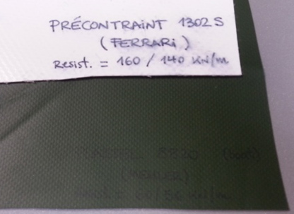
| 4 | Use of latest generation reinforced materials |
| 5 | Assembly system using simple elements, without the need for specialization |
| 6 | Positioning system that does not require helicopters or heavy cranes |
| 7 | Assembly time measurable in hours, not days or months |
| 8 | Logistics and transportation volume of about 12 m3. This volume allows to create a stock of dozens of bridges in the space currently occupied by only one of the alternatives. |


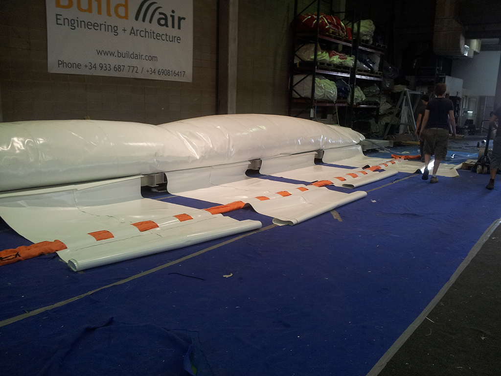
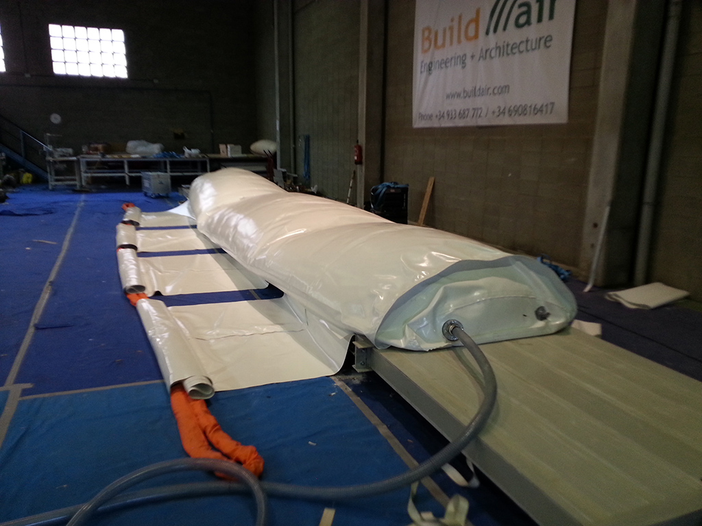
Unlike other fast-deployment bridge alternatives, the assembly of the Air-Bridge can be done easily in about 8 hours with a team of 8 workers. The process takes place in an inverted position on the ground; it is identical for the two beams and can be performed in parallel (except turning maneuver and positioning).
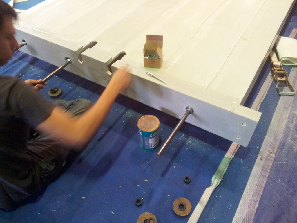
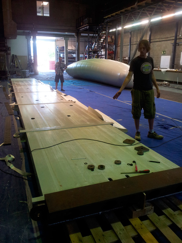
Assembly steps:
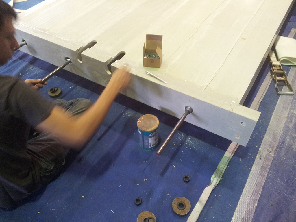
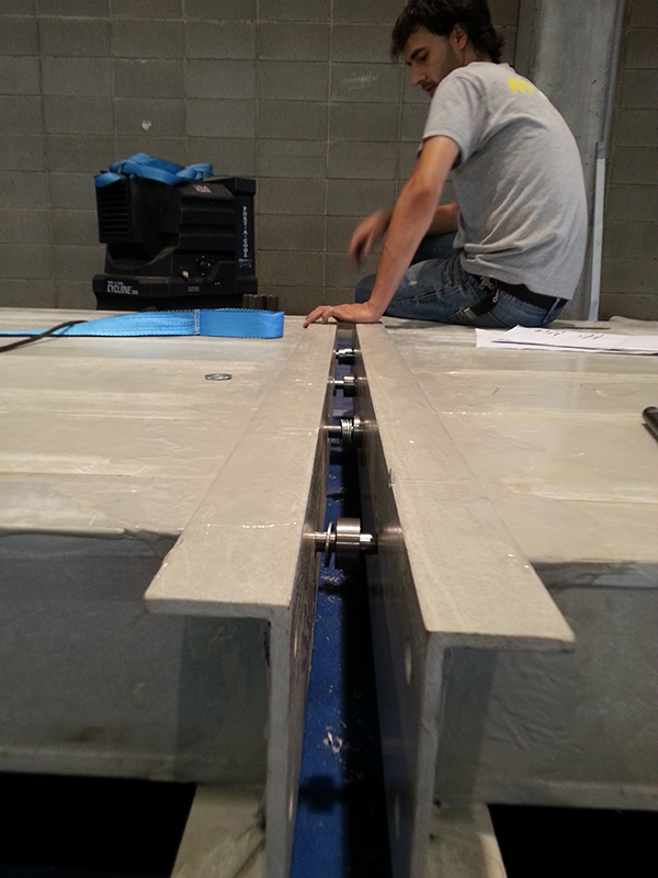
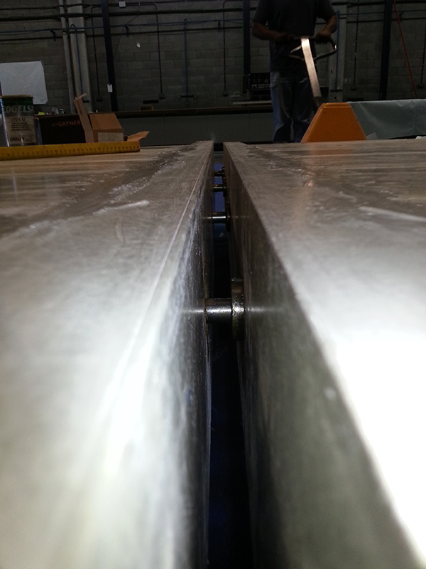
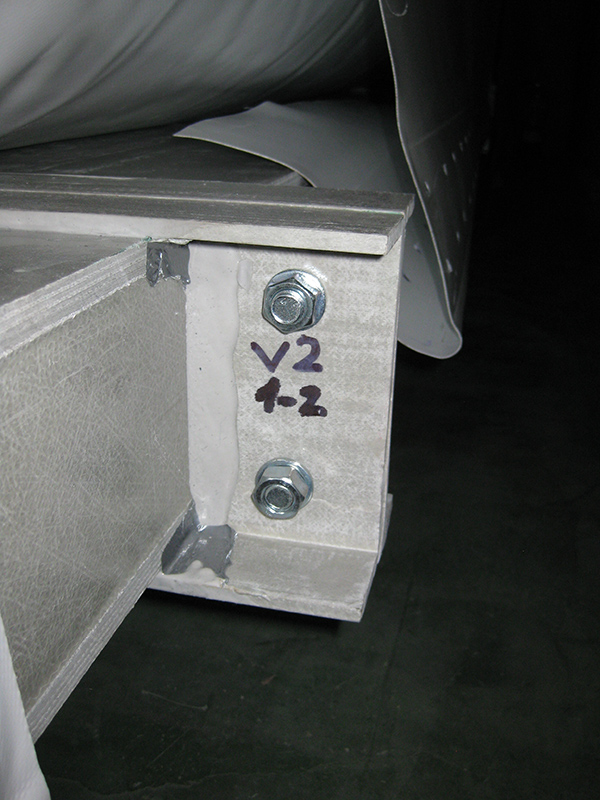
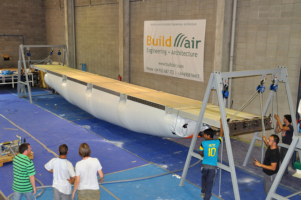
The panels are aligned and the longitudinal steel bars are introduced through the joint area, adding also the shear transmission washers. The longitudinal bars are joined with couplings into the holes provided for this purpose on the board. The steel supports are finally added to the ends and the rods are tightened by nuts, for prestressing.


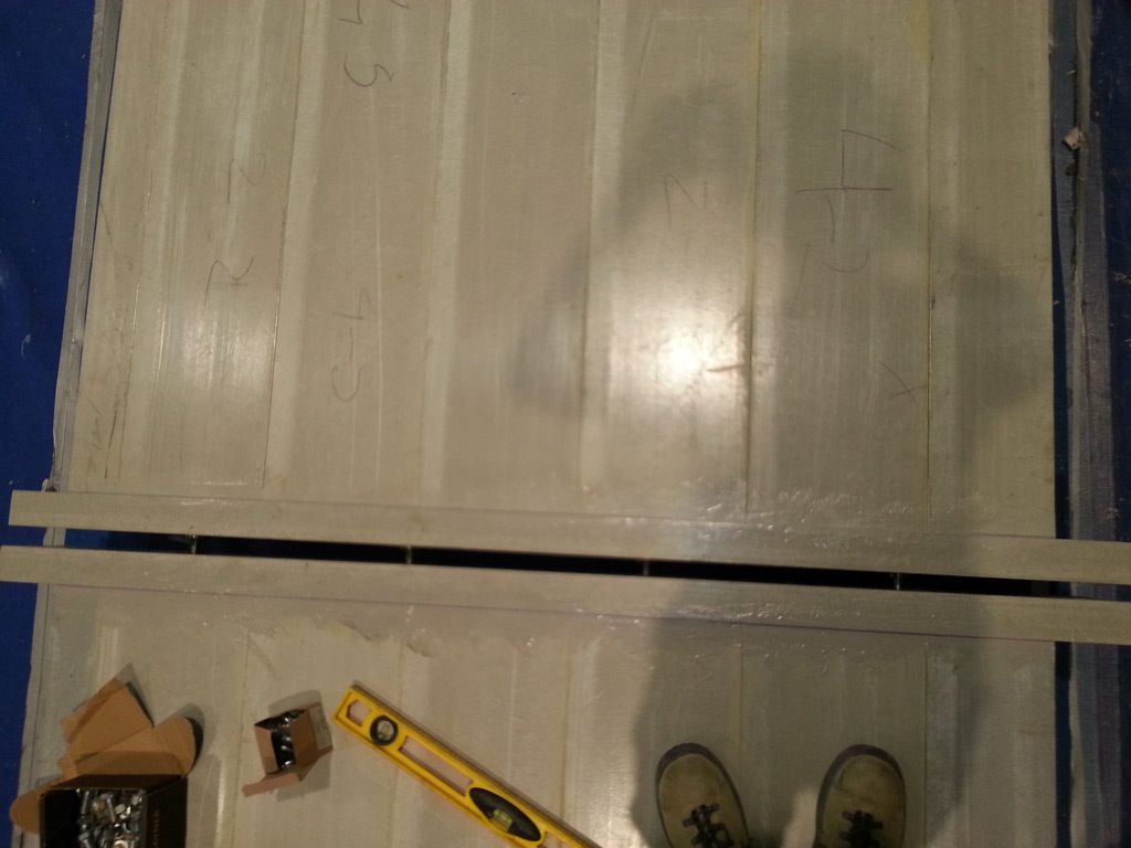
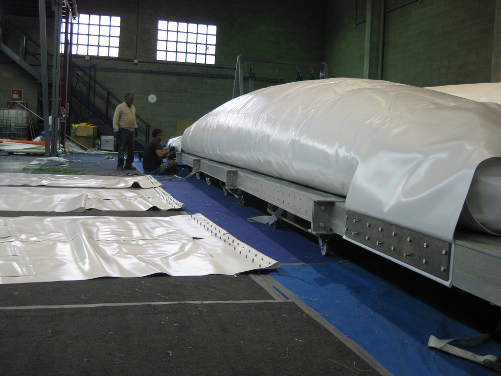
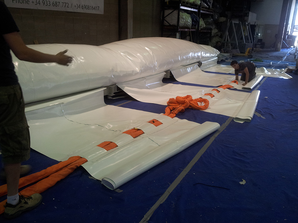
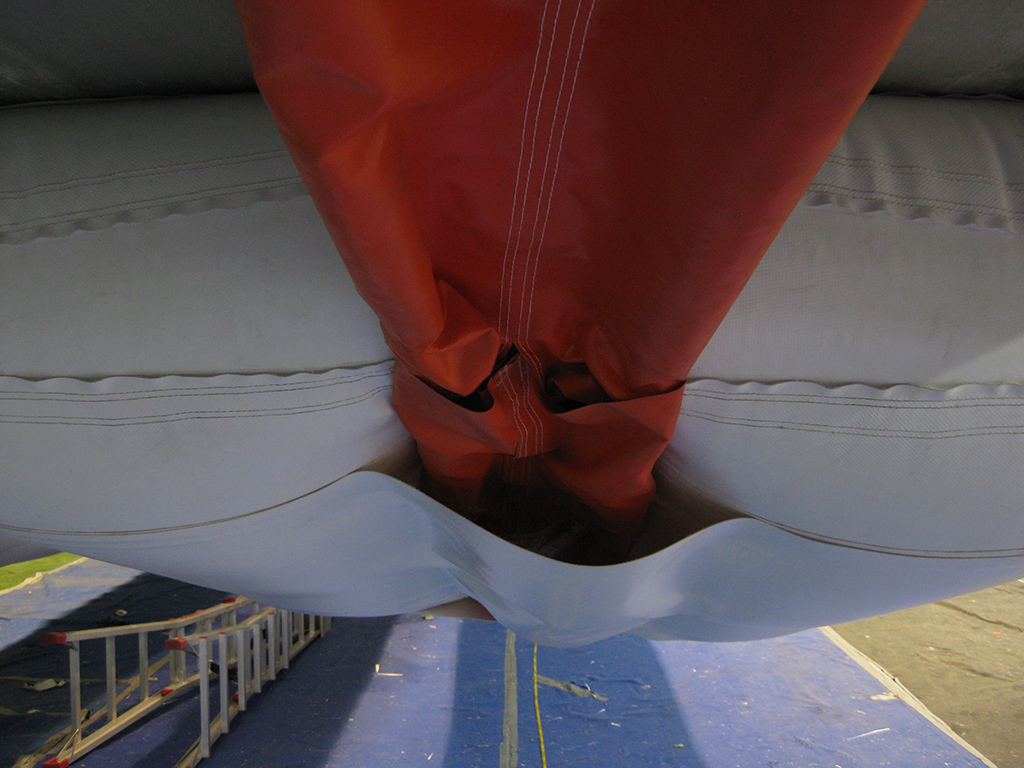
The tube is extended and centered on the deck. Later, the tie bands are fixed to the side of the deck by using bolted steel plates. Joints between panels are also screwed.

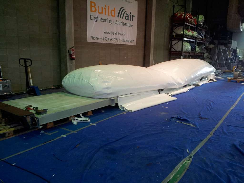

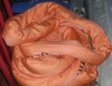
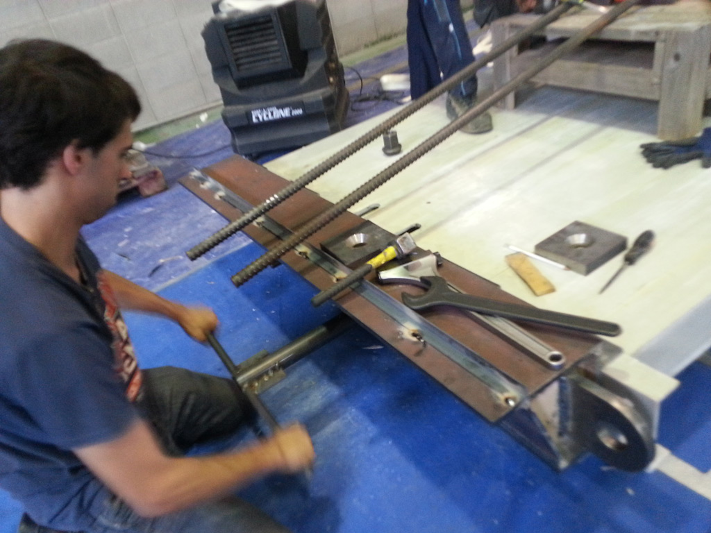
With the tie bands fixed on the deck side, the sling is placed through the dowel pins designed for this purpose. Later, everything is placed over the tube and the strips are fixed to the other side. Once it is fixed and the tube is semi-inflated, the sling is anchored to the ends of the beam.

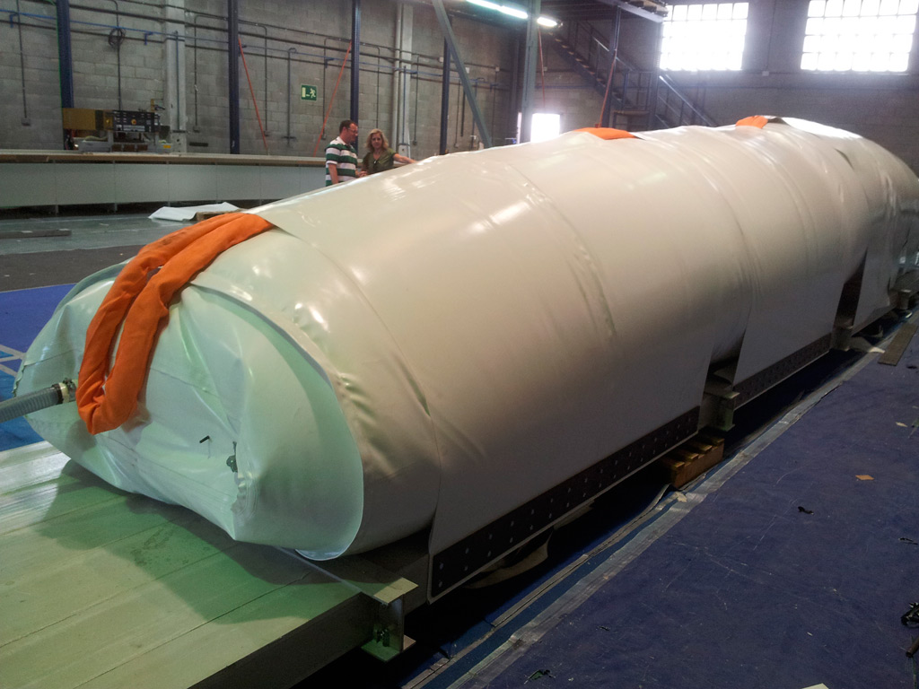


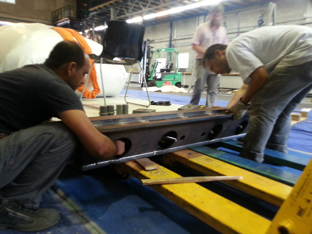
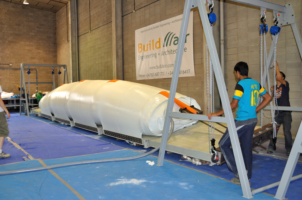
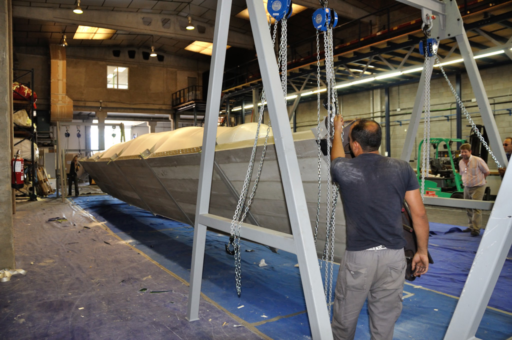
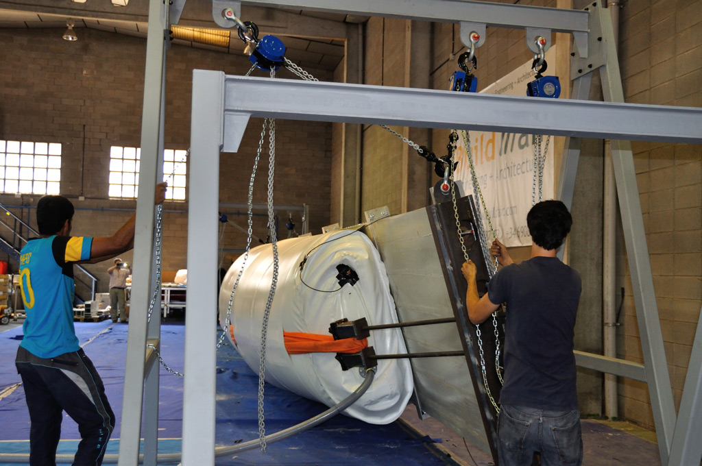
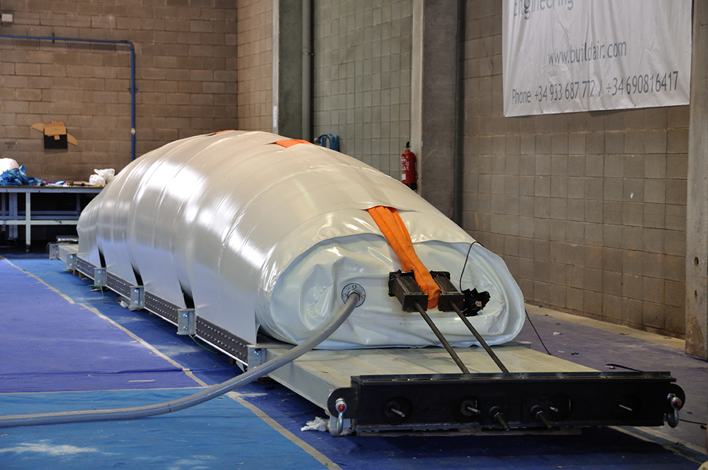
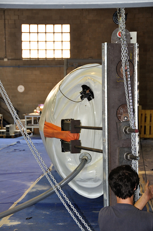
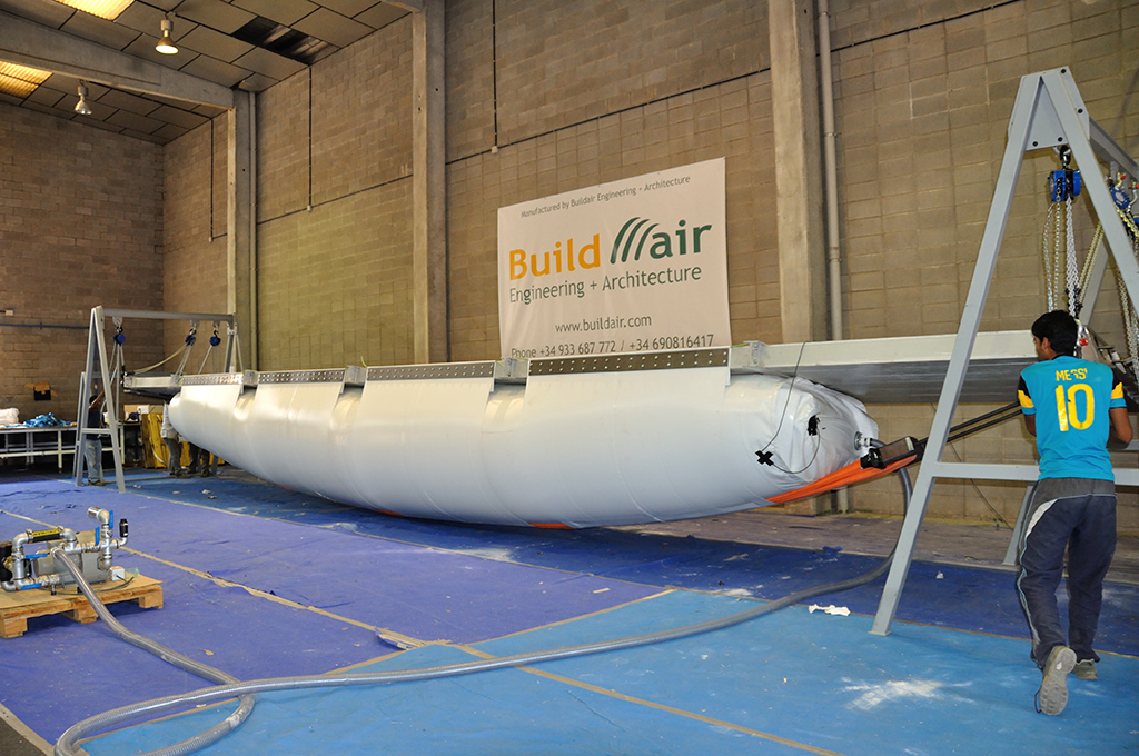
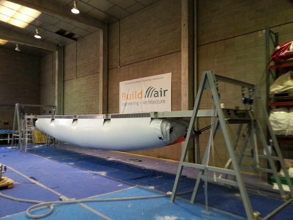
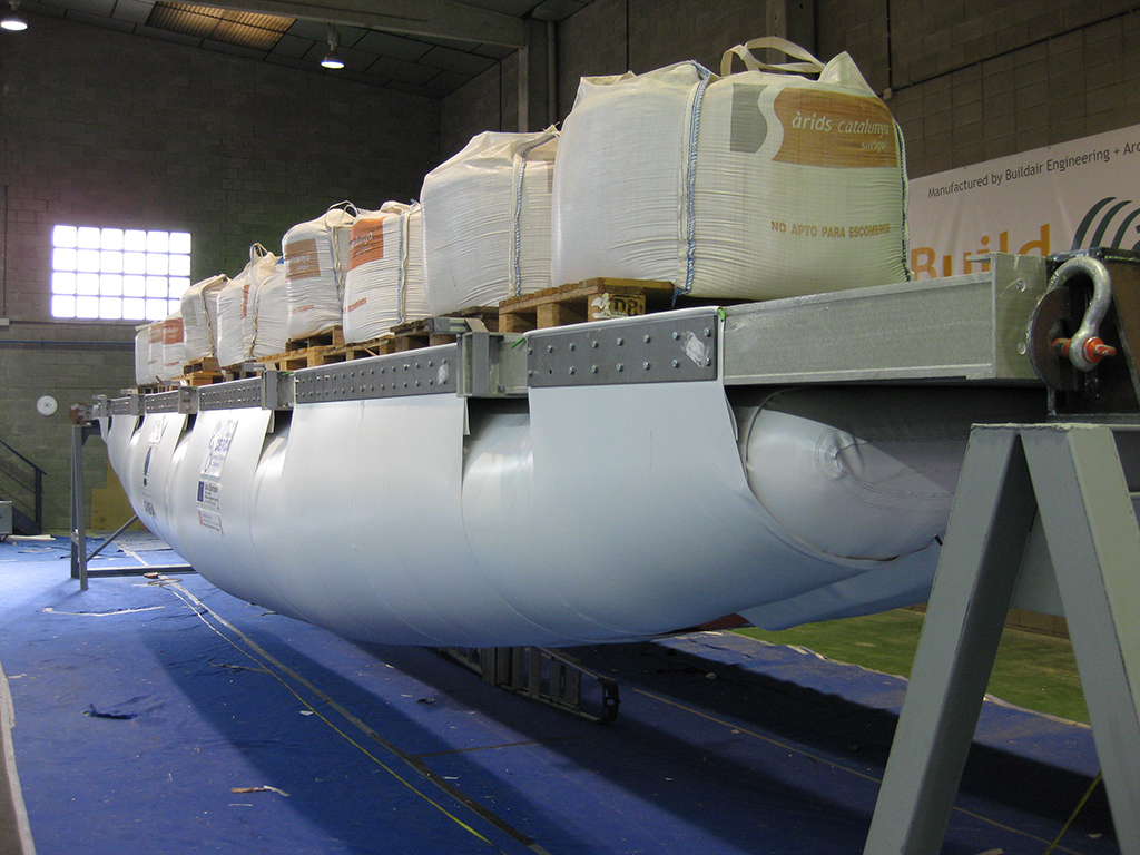
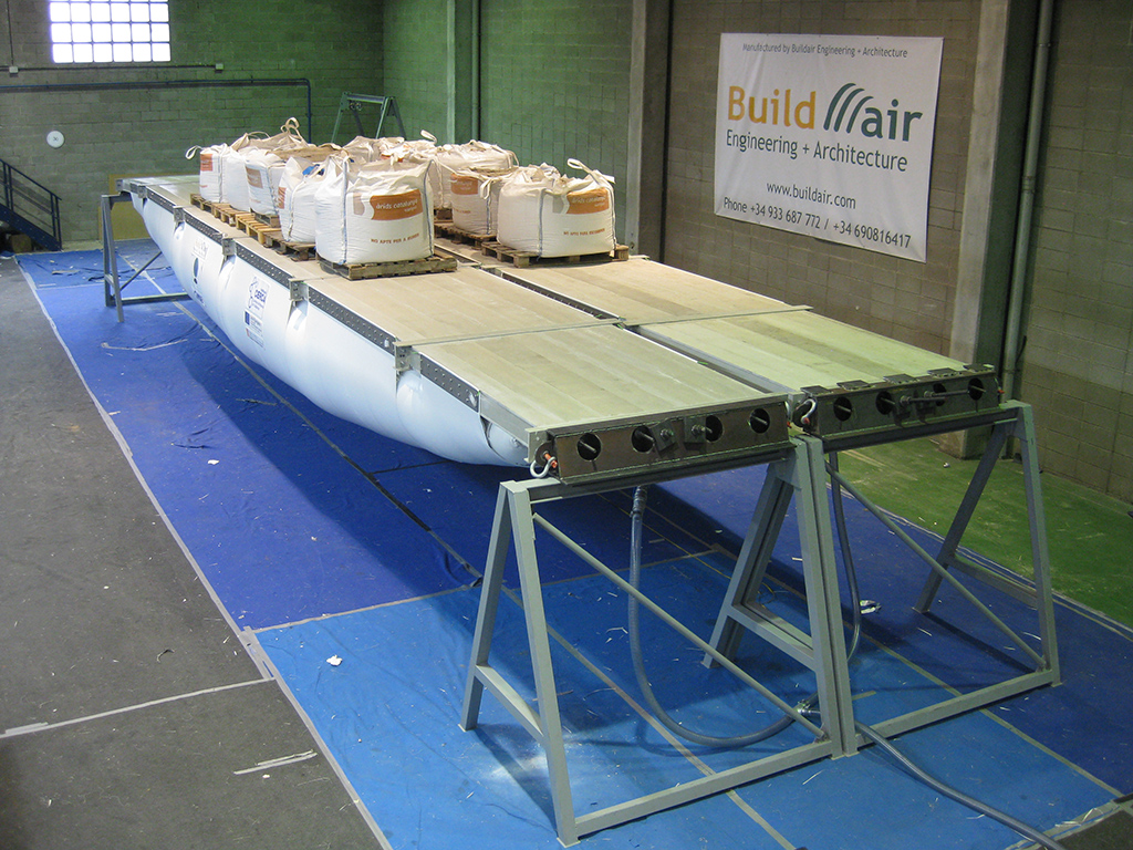
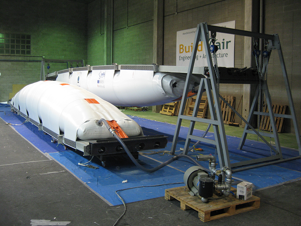
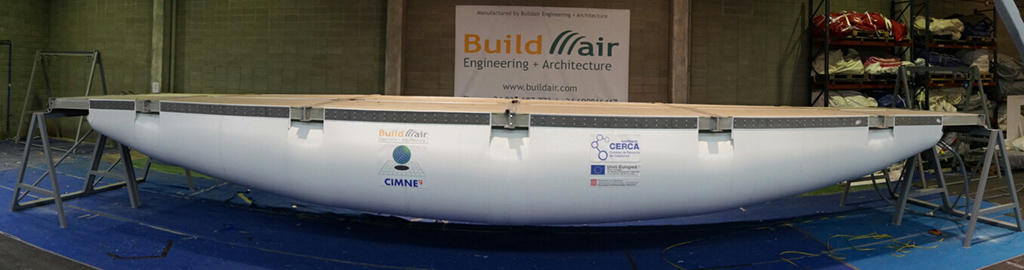
Once the beam is assembled upside down, the turning maneuver is done. For this purpose, two porticos with several hoists that are anchored to the sides of the steel supports of the beam have been designed, allowing the rotation and lifting of the air-beam. Once rotated, the beam is positioned on trestles designed for the tests. In the pictures below the whole process can be seen, ordered from left to right and top to bottom.


Assembly video
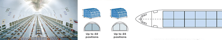
Since the bridge must be easily dismantled and portable, it is composed of pieces that fit into standard pallets of 88"x54" for freight aircraft (2,235 x 1,372 x 1,70 m3).
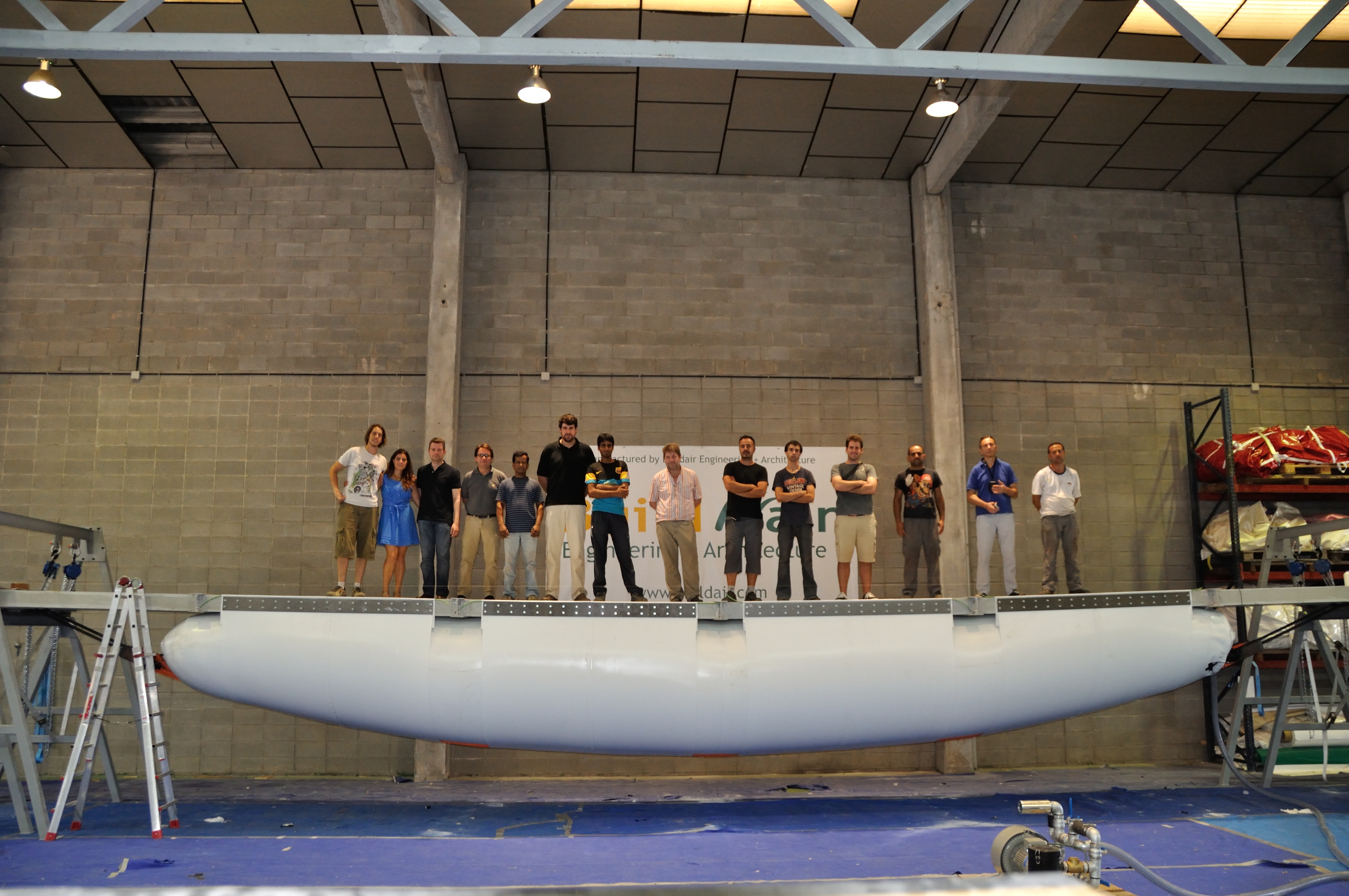
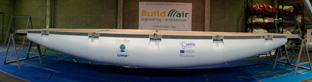
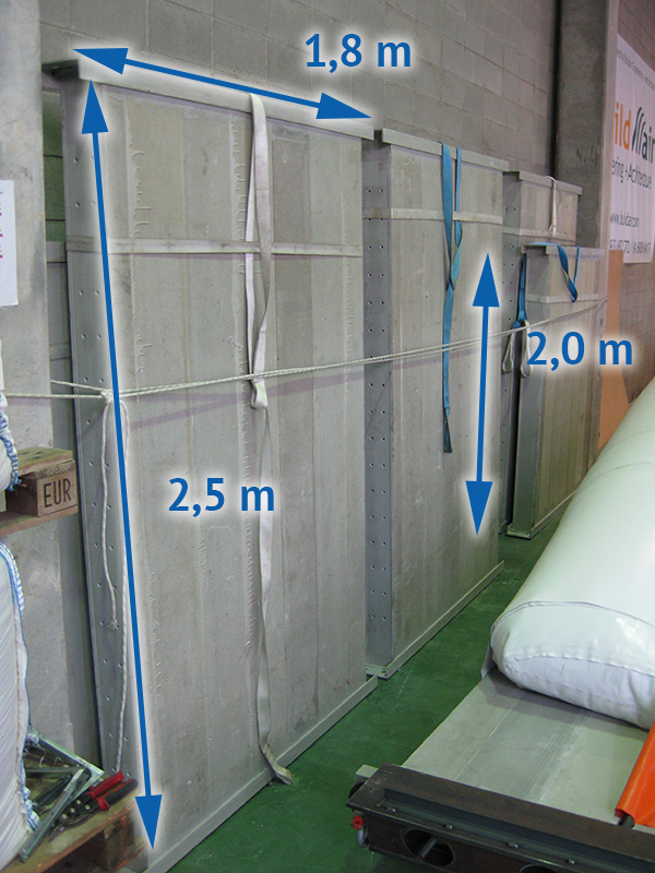
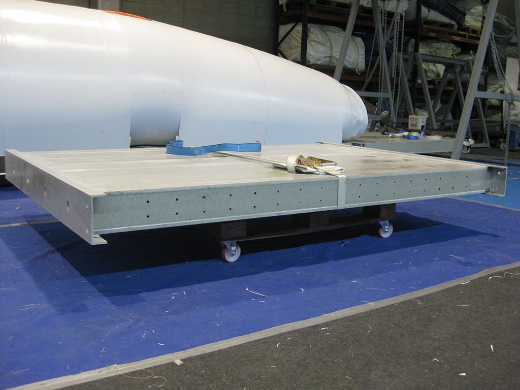
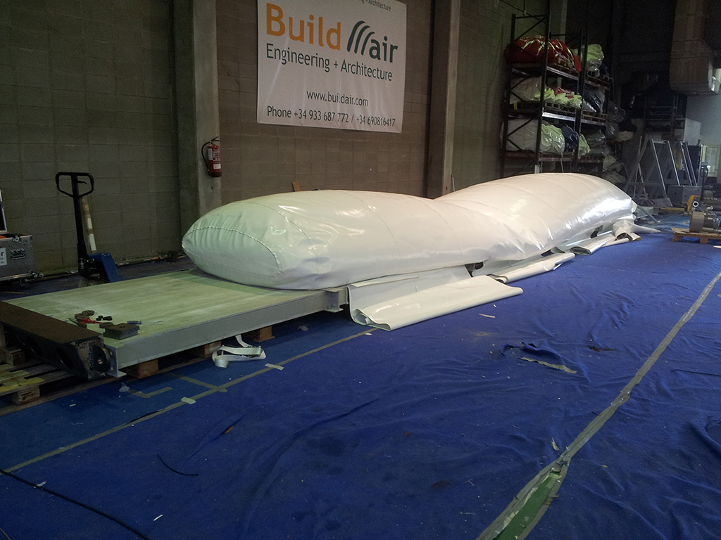
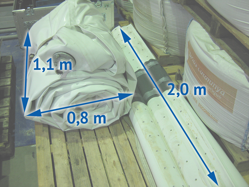
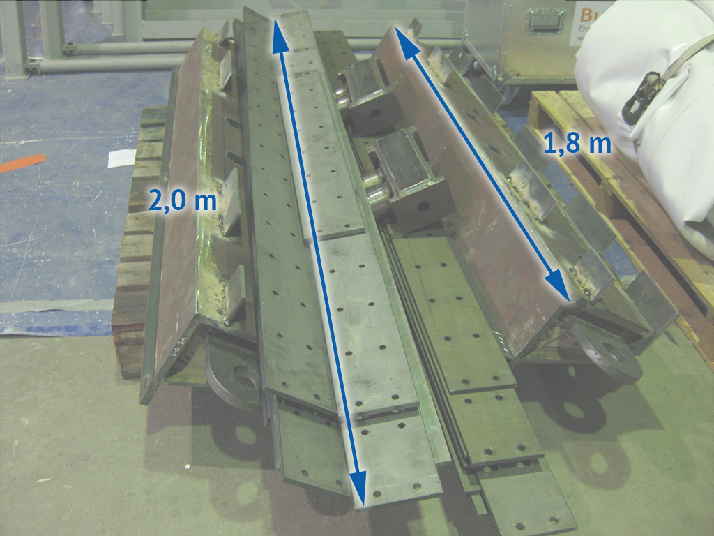
Here are some images of an Air-bridge beam in the upside down position, and beside the other dismantled piece by piece.

The inflatable tube of the air-beam occupies approximately 0,7 m3, when folded, compared to the volume of 19 m3 when inflated. The final panels will measure 2,00 m x 1,70 m.

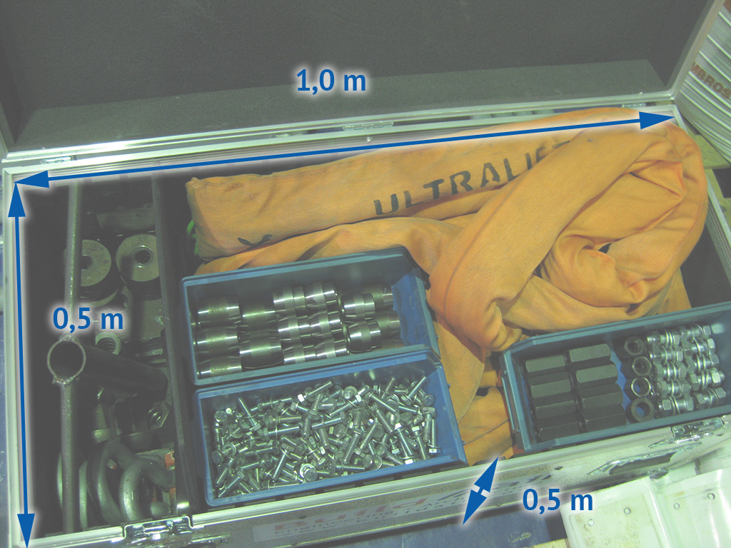
The sling and all the screws, couplings, shear transmission washers, metal plates and tools fit into a box of 1,00 m x 0,50 m x 0,50 m. The steel supports and anchoring plates measured as maximum 2,00 m in length and fit on a standard pallet.

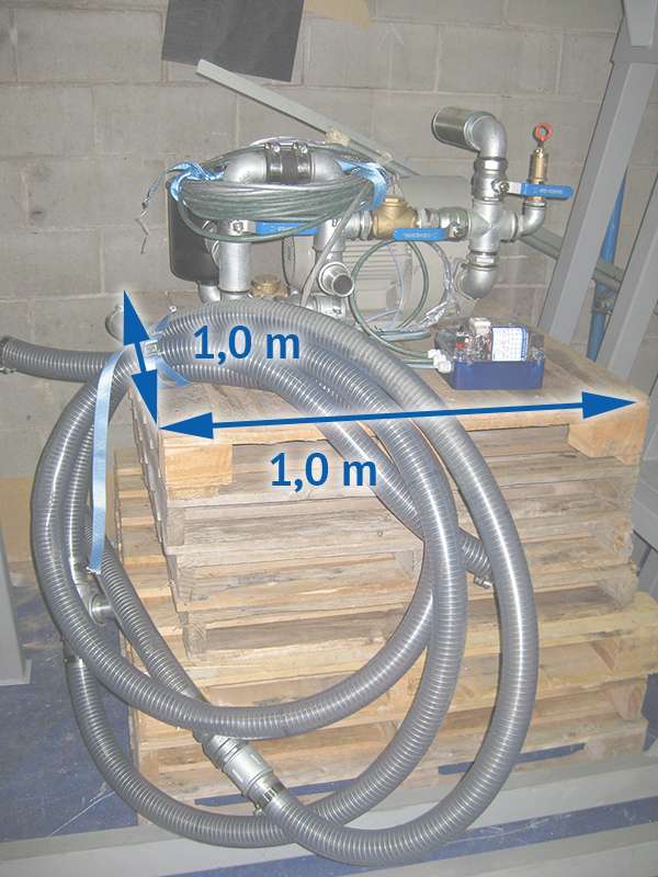
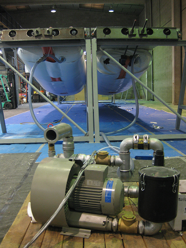
Finally, the blowing engine weighs 40 kg and fits well on a pallet of 1,00 m x 1,00 m. The air-ducts can be folded and stored in very little space.
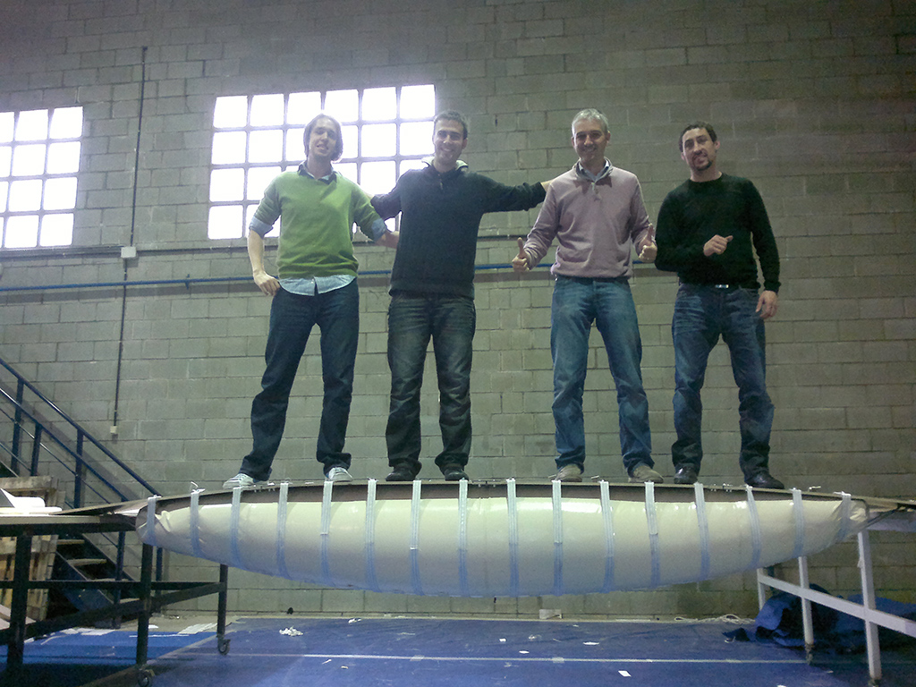
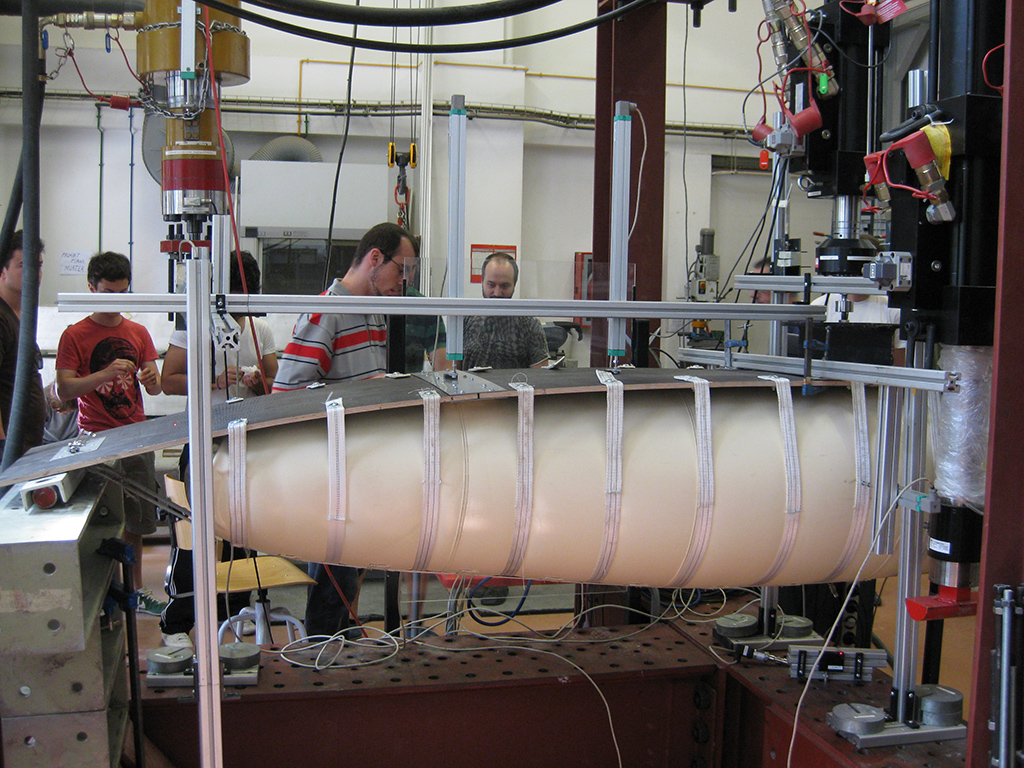
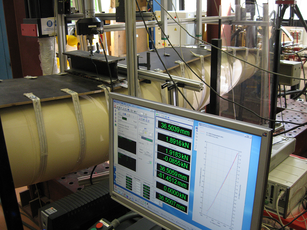
In a previous study before the design, calculation and manufacturing of the real-scale prototype, a scaled prototype has been manufactured. This Tensairity® beam prototype is 4 meters long and is formed by an inflatable tube of 0,5 meters in diameter at the central section. This prototype has been manufactured with two objectives: on one hand to validate the concept of Tensairity® technology as a real physical prototype, and on the other hand to perform a laboratory load test to validate the results obtained in the numerical simulation of a Tensairity® beam by calculating with the Stampack software.


Stampack is a software based in the finite element method, result of the continuous research work carried out by several researchers at the International Center for Numerical Methods in Engineering (CIMNE) in Barcelona. The program is based on explicit finite element method and used for numerical simulation of metal forming processes. Despite being designed for these kinds of problems, simulations with membrane-type materials can be done with a few changes in the program code, materials that are present in inflatable structures.
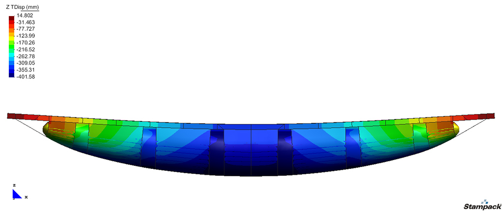
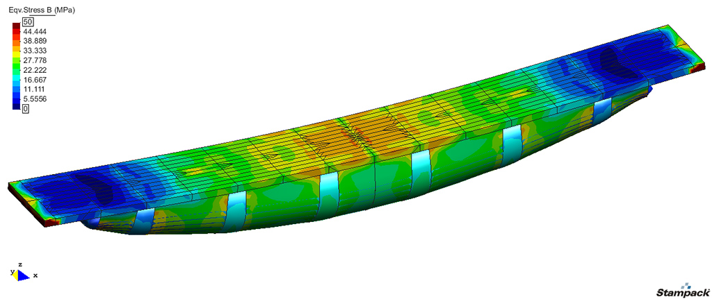
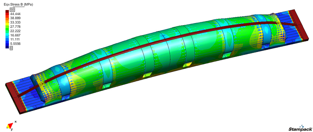
After the detailed design of the air-beam, a finite element modeling of the structure has been carried out in order to obtain the deformations and stresses in the elements caused by the application of the design load. Applying the MLC 30 vehicle load on the air-beam, the center of the deck has a maximum deflection of 327 mm.
Simulation video
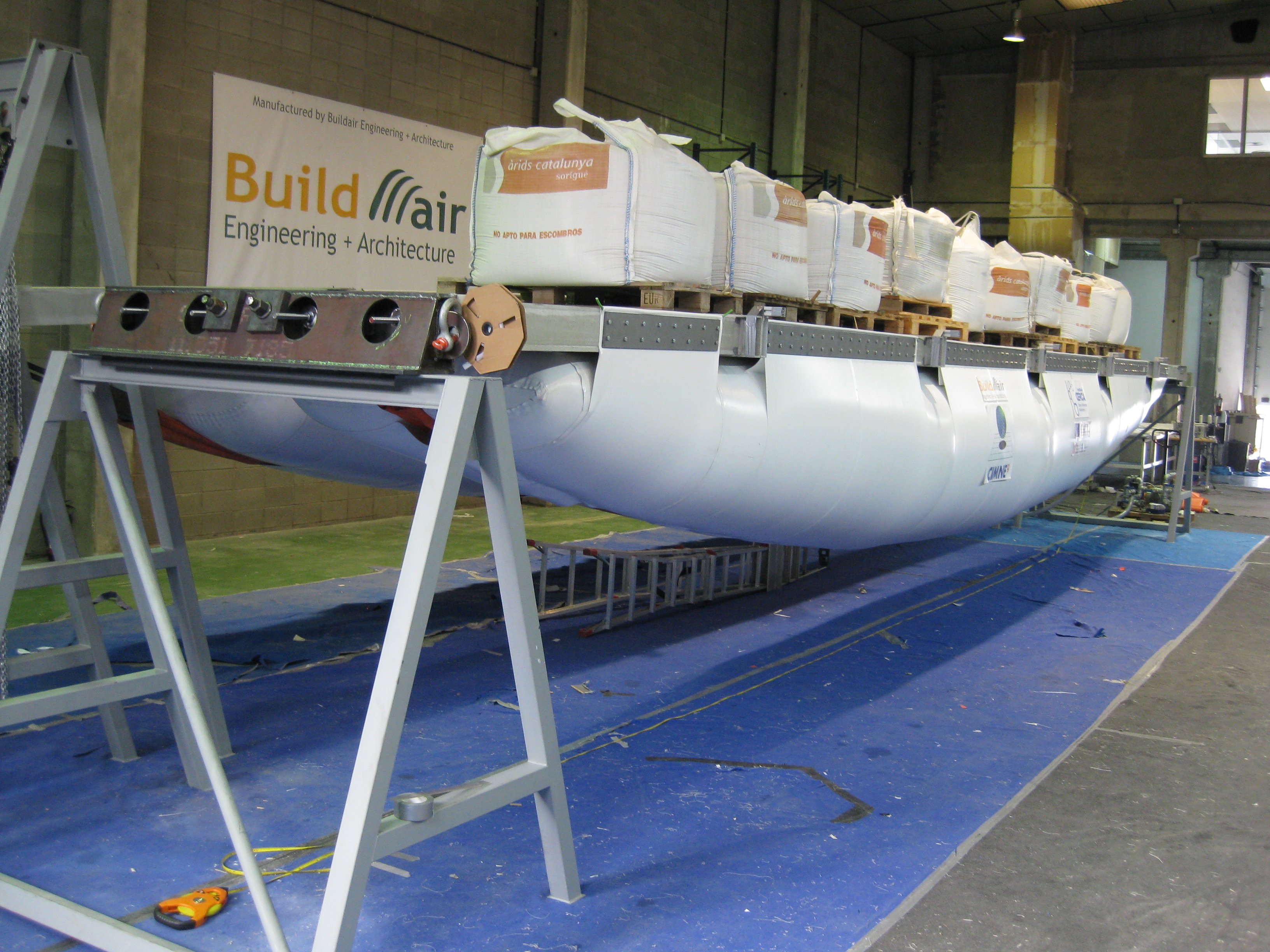
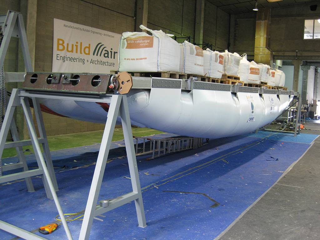
In order to validate the results of the numerical simulation, the full-scale air-bridge prototype has been tested. Several load tests have been carried out with a distributed load over the deck of 10 tn (10 sandbags of 1tn each), with a tube inflation pressure of 175 mbar. The results obtained measuring the deflection in each of the sections between panels, under load increments of 1 tn, are the following.
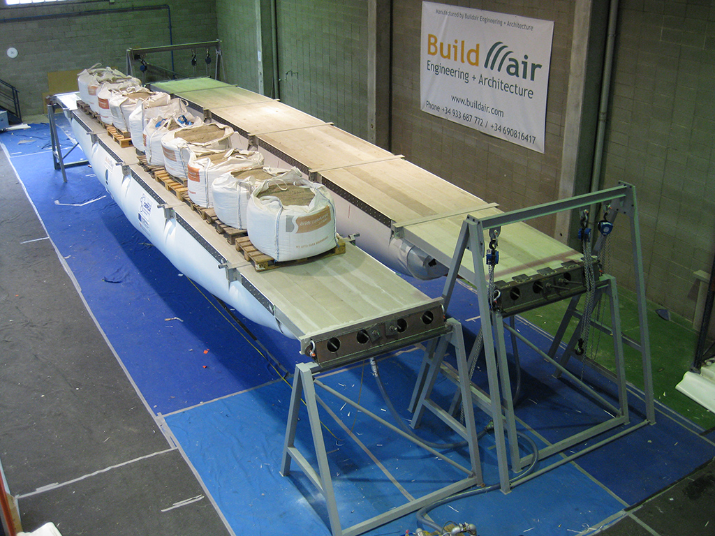
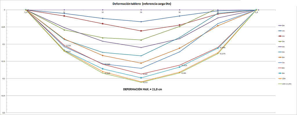
As it can be seen in the graphs obtained, the maximum deflection at the center of the deck with a load of 10 tons is 21,0 cm. In the initial phase calculation, numerical simulations estimated a deflection of the deck of 32,7 cm (15 tn in the air-beam, distributed according to military regulations for MLC 30 vehicle). If we assume a linear behavior in the tests, with 15 tn (and distributed load) we would get a theoretical deflection of 31,5 cm, which is very similar to the one obtained by software calculations.
Air-Bridge test video
Because of the special characteristics of this type of bridges and its international nature, the reference design requirements are taken from the military code “Trilateral Design Test Code”, which is based on the MLC classification of vehicles. In particular, the vehicle that has been chosen for the design is the MLC 30, whose specifications are:
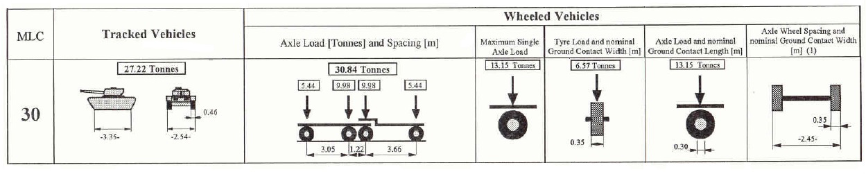
The military code “Trilateral Design Test Code” is a code agreed between Germany, UK and USA, also query for the “Quadripartite ABCA (American, British, Canadian, Australian and New Zealand Armies’ Program)” and it is fully focused on deployable bridges, which are identified as standard bridges within the U.S. military field.

The International Centre for Numerical Methods in Engineering (CIMNE) is a research organization in Barcelona, Spain created in 1987 as a Consortium between the Catalan Government (Generalitat de Catalunya) and the Universitat Politècnica de Catalunya (UPC). CIMNE is a CERCA center.
CIMNE employs some 180 scientists and engineers from different technical fields and nationalities in the development and application of numerical methods (basically, the finite element method) to a wide class of engineering problems.
In the last 27 years CIMNE has taken part in over 450 RTD projects with over 200 companies and organizations. Some 150 of these projects have received EC support through FP3-7 programs. CIMNE has been the coordinator of some 45 EC funded projects.
The outcome of the research at CIMNE is recorded in over 1000 scientific publications, technical reports and educational software codes published by CIMNE. CIMNE also publishes books and monographs on subjects related to computational mechanics. CIMNE has also successfully organized some 200 courses and seminars and 80 international conferences.
Buildair Engineering and Architecture SA (Buildair) is a SME in Catalonia leader in the design, engineering and manufacturing of inflatable structures with particular emphasis on covering large spaces. Created in 2001, Buildair aims to offering the market the latest technologies in design and construction for inflatable structures. The company has designed many applications for the temporary coverage of large spaces. In addition, it has produced these types of structures for different engineering applications.
Through the continuous work of their research and development team, Buildair can ensure that all products and services are unique and optimal for their clients. Their products can be adapted to any customer needs.
The use of an innovative inflatable structure enables their customers to solve different engineering and architecture needs. The goal is to provide with a wide range of products that meet the demands of specialized clients.
The CERCA Institute is the Government of Catalonia’s technical service and its means for supervising, supporting and facilitating the activities of the research centers in the CERCA system. Set up as a foundation, it was created in 2010 to respond to the commitments of the Catalan Agreement on Research and Innovation:
«The Government of Catalonia will create the Agency for the Research Centers of Catalonia using existing resources with the purpose of responding to the specific and singular needs that emerge from the structural development, monitoring and funding of Catalan research centers.»
The model for the CERCA research centers of Catalonia has developed quantitatively and qualitatively over the last ten years, and has reached levels of scientific excellence in various areas. It is a model characterized by fluid and self-governed management structures, the attraction of talent, and efficiency in obtaining competitive funding founded on scientific activity of the highest degree. Now, the challenge is to continue growing in a rapidly changing context in which numerous opportunities can be found.
The purpose of the CERCA Institute is to ensure that the Catalan research centers system is properly developed; to encourage and maximize synergies, coordination between centers and strategic cooperation; to improve the positioning, visibility and impact of the research carried out and to facilitate communication between public and private agents.
Grants intended to support the production of prototypes and the valorisation and transfer of the results of research carried out in the centers that belong to the Research Centers of Catalonia (CERCA) system.
Valorization projects can be of an individual or a collaborative nature. For collaboration projects, one of the CERCA centers must act as coordinator and the rest as participants.
Projects eligible for the grant must include structured activities that demonstrate successful proof-of-concept testing, using prototypes, pilot scales, pre-industrial tests, clinical or pre-clinical tests, among others, and which aid in assuaging uncertainty regarding the technical or commercial viability of the technology being developed.
Approved projects must be carried out in a maximum two-year period, starting from the date on which the grant is accepted by the applying entity.
The call’s maximum budget was €1.500.000 in 2011, with ERDF funding (European Regional Development Fund).


Air-Bridge test video
Simulation video
Assembly video